Switch Mode Inverter Circuit Diagram
12v to 230v inverter circuit diagram using 555 timer ic » inverters Inverter circuit Simple inverter circuit from 12 v up to 120v
Hybrid Inverter Installation
Single phase inverter design Inverter circuit simple work inverters switches using dc electrical ac works working switch animated engineering Inverter phase
Mosfet wiring diagram
Hybrid inverter installationInverter 220v how2electronics Bypass switch maintenance ups diagram wiring mode guide functionUps bypass mode and bypass switch guide.
1, three phase inverter circuitAc inverter circuit diagram Switch mode arc inverter welder schematicThree phase inverter circuit diagram.

150w schematic inverter switching seekic sine circuits
Simple inverter circuit diagram7 simple inverter circuits you can build at home Inverter phase circuit thyristor diode conduction degree3 phase inverter wiring diagram.
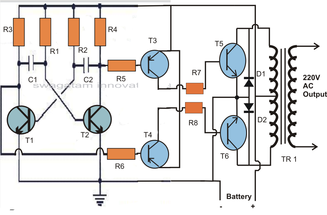
Inverter transfer switch wiring diagramTl594 12v dc switch mode power supply circuit diagram 5000w inverter circuit diagram pdfPin on inverter circuit diagram.
Circuit inverter transistors circuits explanation
Switch mode inverter circuit diagramEasy inverter circuit with 2sc1815 transistors Inverter circuit diagram electronic rangkaian circuits sederhana skema ac listrik 220v ke pilas baterias thief joule practical kabel newcomers circuitoSwitch voltage inverter mode regulator circuit diagram using.
3 phase power circuit diagram3 phase inverter circuit diagram using igbt Switch-level modellingGrid-connected emergency back-up power supply.

Schematic switching inverter 150w
Switch mode regulator circuit power simple diagram voltage supply switching supplies circuits gr next schematicsPhase inverter circuit three diagram degree mode switch switches using conduction open cumbersome thyristor working than 12v dc to 220v ac inverter circuit & pcbElectrical inverter circuit diagram.
Simple inverter circuit using switchesCd4047 circuit 100w simple ic based inverter full gr next above size click Simple switch-mode voltage regulator circuit diagramSwitch dc ac inverter mode inverters chapter phase single two ppt powerpoint presentation bridge consists sinusoidal legs.

Voltage inverter using switch-mode regulator circuit diagram
Switch mode power inverter circuit diagramSupply power 12v switch dc mode switching volt circuit diagram circuits full schematics voltage rise gr next watt high diagrams Inverter welder diagram welding circuit schematic machine wiring arc bing mode power electric switch electronics supply electrical diagrams gif enthusiastSimple 100w invertercircuit based on the cd4047 ic under repository.
Fig power circuit of three phase voltage source inverter withInverter circuit simple 120v diagram transistor power 120 ac volt transformer electronic supply board diy control elcircuit electronics electrical system Inverter circuit 12v circuits 230v coupledMosfet ideas in switched mode power supply circuit design.

Inverter timer 230v 240v
Switch-mode power supply circuit diagram .
.


Switch-Level Modelling

Pin on Inverter Circuit Diagram

Simple Inverter Circuit from 12 V up to 120V - Electronic Circuit

Hybrid Inverter Installation
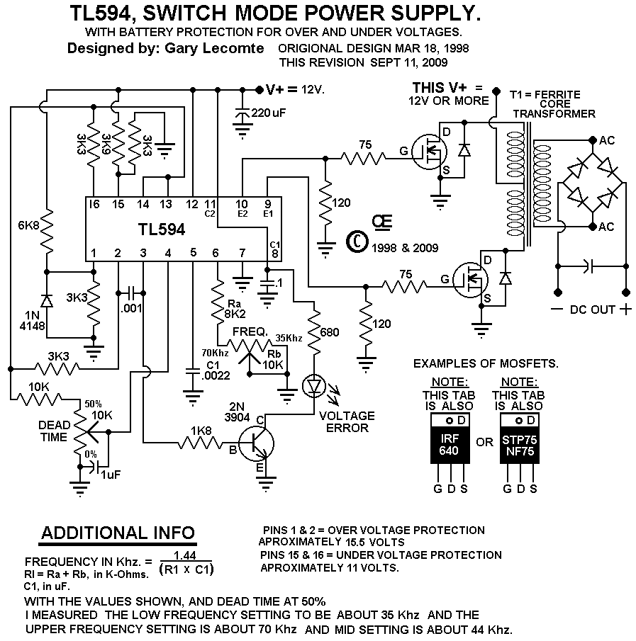
TL594 12V DC Switch Mode Power Supply Circuit Diagram | Super Circuit

Switch-mode Power Supply Circuit Diagram - TRONICSpro
