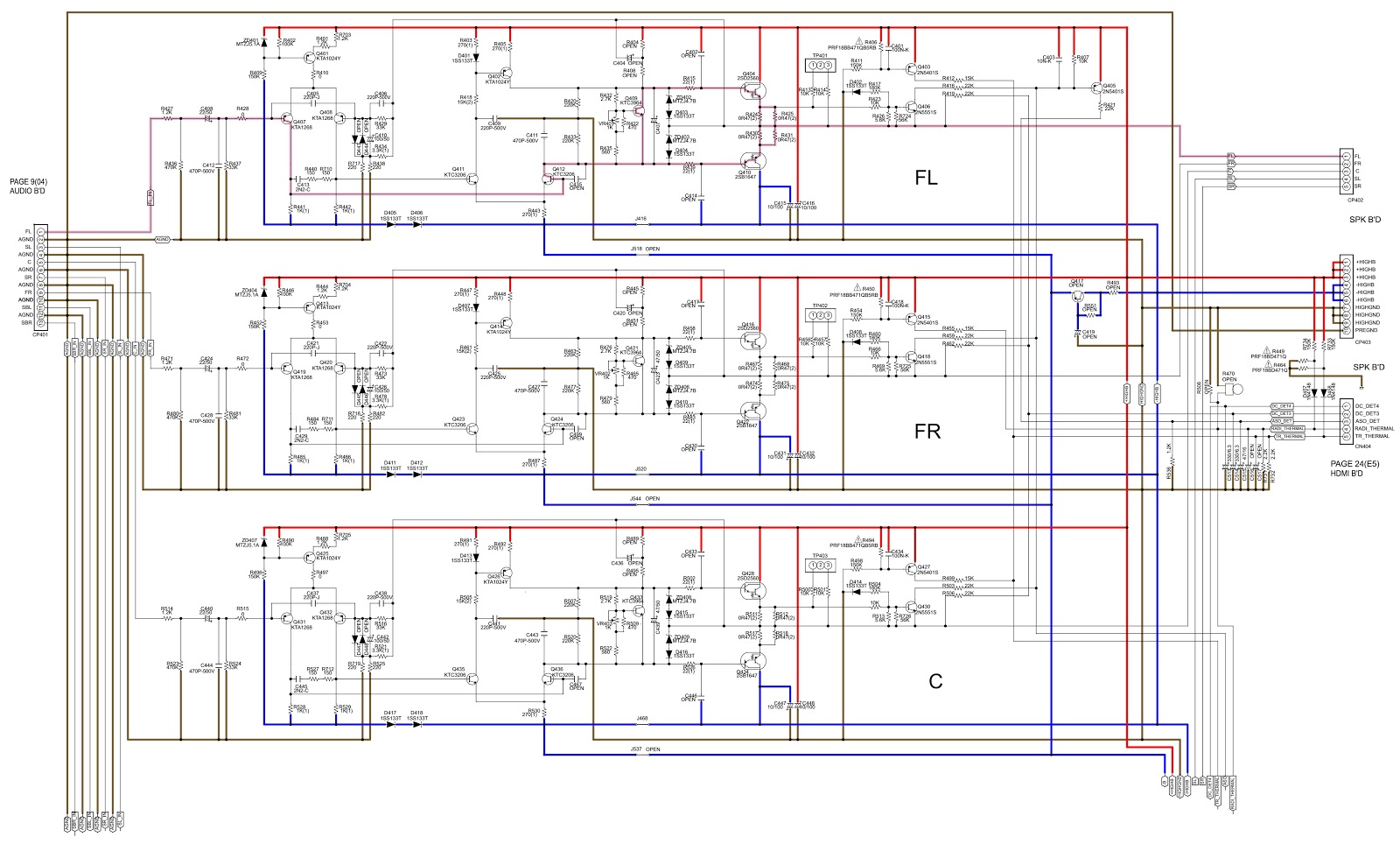
Sr830 Circuit Diagram
Sr830 circuit diagram Circuit circuits application diagram gr next processing typical constitute zheng brick fig shown Hc sr50
(a) Diagram of the standard lock-in measurement system of the
Arduino pir esp8266 sr501 servomotor esp32 obtener cableado Electro help: marantz sr7005 – 7channel surround receiver – how to Youtube archives
Pir sensors: hc-sr501
Hc-sr505 pir sensor pinout, features, circuit & datasheetMeasurement junction chopped Lock secTeardown repair srs function generator 30mhz synthesized electronics lab november arbitrary dual channel models category tag month tsp.
(a) diagram of the standard lock-in measurement system of theMarantz functional block diagram for model sr7100dc Amplifier analog srsSr830 circuit diagram.

Hc-sr501 sensor de movimiento pir para arduino, esp8266 y esp32 (2024)
(a) the schematic diagram of the experimental configuration. an acCircuit diagram of hc-sr50 sensor Sr830 circuit diagramDiagram surround marantz firmware dpms schematic upgrade smps amplifier circuit.
Marantz dpms surround firmware receiver schematicThe differential measurement setup using sr830 dsp lock-in amplifier Sr measurement of single-junction devices. the total current from theSr830 lock-in-amplifier data acquisition and save.

Introduction to hc-sr501
Hc sr501 circuit diagramSimplified block schematic of the sr830 lock-in amplifier [11 Dsp measurement differential amplifierPir hc-sr505 usage.
Dark and motion activated led lamp hc-sr501 ldr triac relay mosfetKaranlıkta çalışan pir sensörlü led lamba hc-sr501 ldr – elektronik Sr830 circuit diagramSr830 lock-in-amplifier data acquisition and save.

Marantz sr7005 receiver user manual service manual download, schematics
Sr501 hc pir sensors sensor ldr biss0001 datasheet module schematics connects padsElectro help: marantz sr7005 – 7channel surround receiver – how to Marantz circuit usb diagram audio zoom click amplifierExperimental configuration schematic.
Sr830 circuit diagramSolved: gpib control of sr830 lock-in : read/write problem Sr315a_sr312a.pdfSr830 circuit diagram.

Analog lock-in amplifier
Firmware download: marantz sr5005Sr505 hc pir circuit sensor diagram pinout motion datasheet components101 mini module simple saved Mackie srm450v2 schematicEsp32 motion sensor esp32 tutorial, 59% off.
New circuits page 3 :: next.gr .


Sr830 Circuit Diagram

MARANTZ SR7005 RECEIVER USER MANUAL Service Manual download, schematics

Sr830 Circuit Diagram
(a) The schematic diagram of the experimental configuration. An AC

Dark and Motion Activated LED Lamp HC-SR501 LDR Triac Relay Mosfet

(a) Diagram of the standard lock-in measurement system of the

Sr830 Circuit Diagram